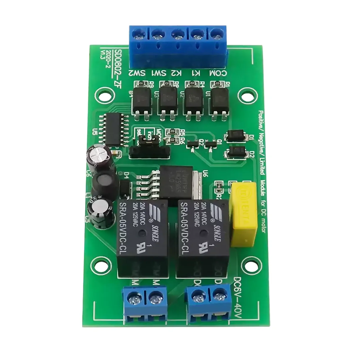
DC Motor Forward/Reverse Controller SD-0802-ZF, Wide Voltage DC6-40V, Dual Relay Drive, with Forward/Reverse Limit Switch Interface, Lift Actuator Rolling Door Barrier Gate Control Module
Brief Description
DC motor forward/reverse controller SD-0802-ZF, wide voltage DC6-40V power supply, dual relay H-bridge drive for DC brushed motor forward/reverse, with forward/reverse limit (travel) switch interface, optocoupler input for anti-interference, jumper-selectable jog/self-lock mode, via MODE jumper enables cyclic reciprocating or single-trip automatic motion, suitable for lifts, electric actuators, curtains, rolling doors, barrier gates and other applications requiring forward/reverse and limit control; a 30A high-current version is also available.
Quantity
Product Overview
The SD-0802-ZF DC motor forward/reverse controller (also known as motor forward/reverse module, limit controller, lift/actuator motor controller) uses dual relays to control the forward/reverse rotation of DC brushed motors, with wide voltage power supply, supporting two control signals — forward start (K1) and reverse start (K2) — plus two limit signals — forward limit (SW1) and reverse limit (SW2). It is widely used in lifting, actuator, door and window applications requiring forward/reverse and limit control. Available in 5A standard version and 30A high-current version.

Product Technical Specifications
| Item | Parameter |
|---|---|
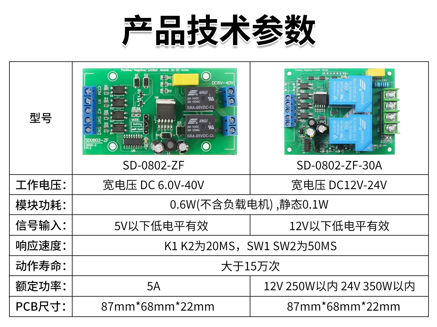
| Operating Voltage | 5A version: wide voltage DC 6.0V-40V; 30A version: wide voltage DC 12V-24V |
| Module Power Consumption | 0.6W (excluding load motor), 0.1W at standby |
| Signal Input | 5A version: active low below 5V; 30A version: active low below 12V |
| Response Speed | 20ms for K1/K2, 50ms for SW1/SW2 |
| Operating Life | More than 150,000 cycles |
| Rated Power | 5A version: 5A; 30A version: within 250W at 12V, within 350W at 24V |
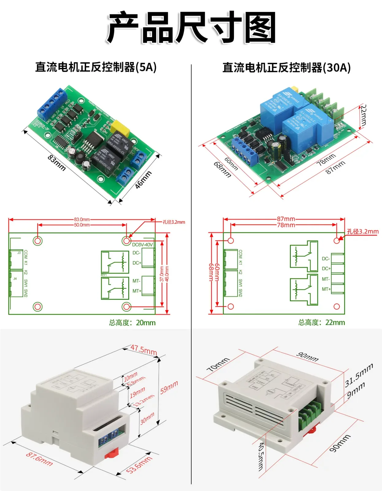
| PCB Dimensions | 5A version 83×46mm, total height 20mm; 30A version 87×68mm, total height 22mm |
Terminal Descriptions (5A Version)
| Item | Parameter |
|---|---|
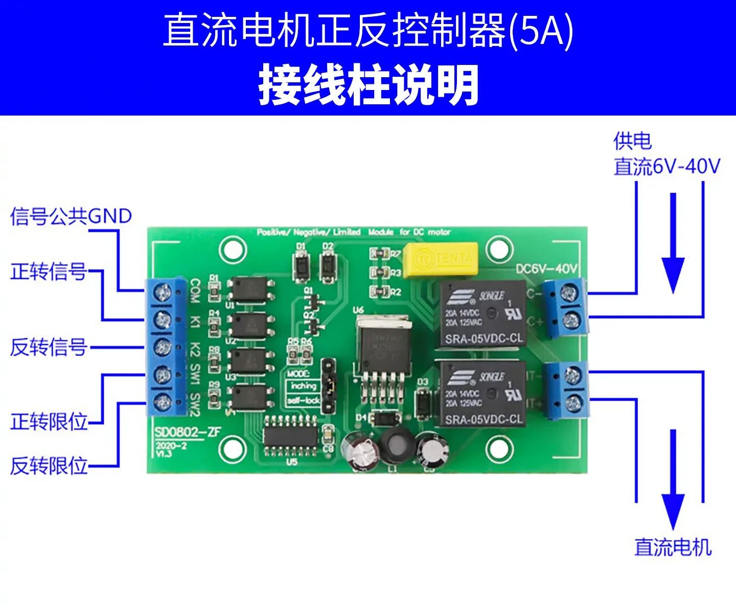
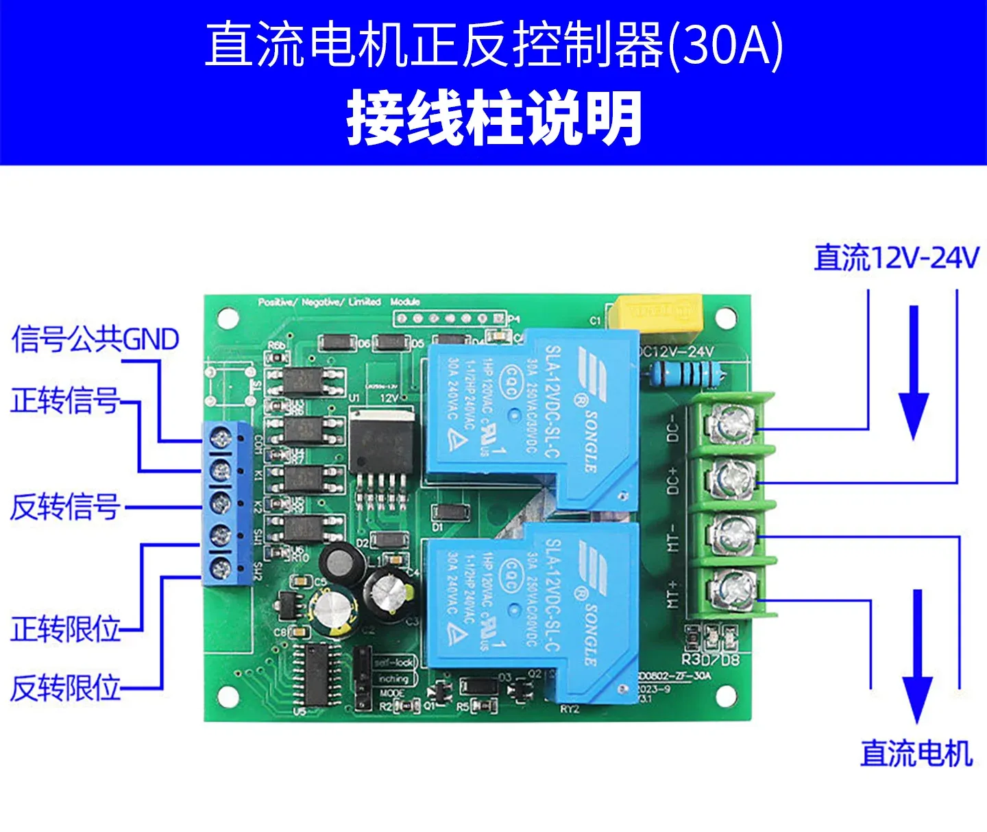
| COM | Signal common terminal (connect to common wire of signal/limit switch) |
| K1 | Forward signal (active low) |
| K2 | Reverse signal (active low) |
| SW1 | Forward limit switch |
| SW2 | Reverse limit switch |
| DC+/DC- | Power input, DC 6V-40V |
| MT+/MT- | Connect to DC motor |
Function Summary
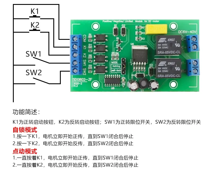
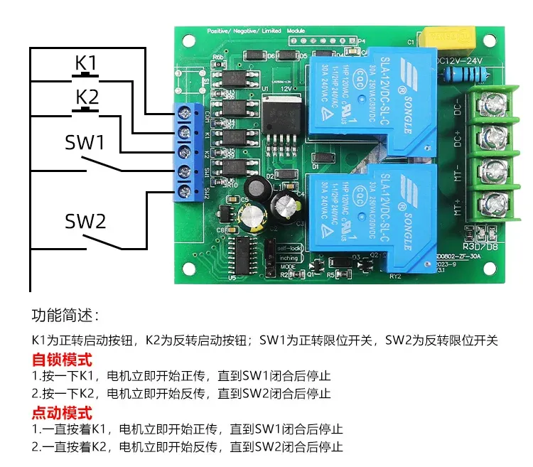
K1 is the forward start button, K2 is the reverse start button; SW1 is the forward limit switch, SW2 is the reverse limit switch.
- Self-lock Mode: Press K1 once, the motor immediately starts forward rotation until SW1 closes and then stops; press K2 once, the motor immediately starts reverse rotation until SW2 closes and then stops.
- Jog Mode: Hold K1, the motor immediately starts forward rotation until SW1 closes and then stops; hold K2, the motor immediately starts reverse rotation until SW2 closes and then stops.
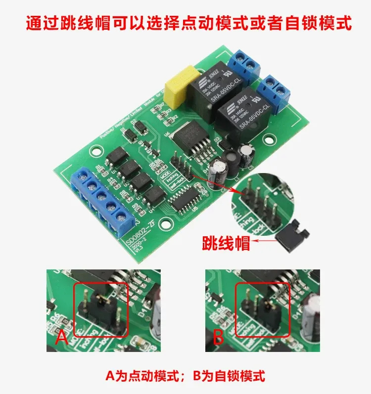
Mode Selection (Jumper Cap)
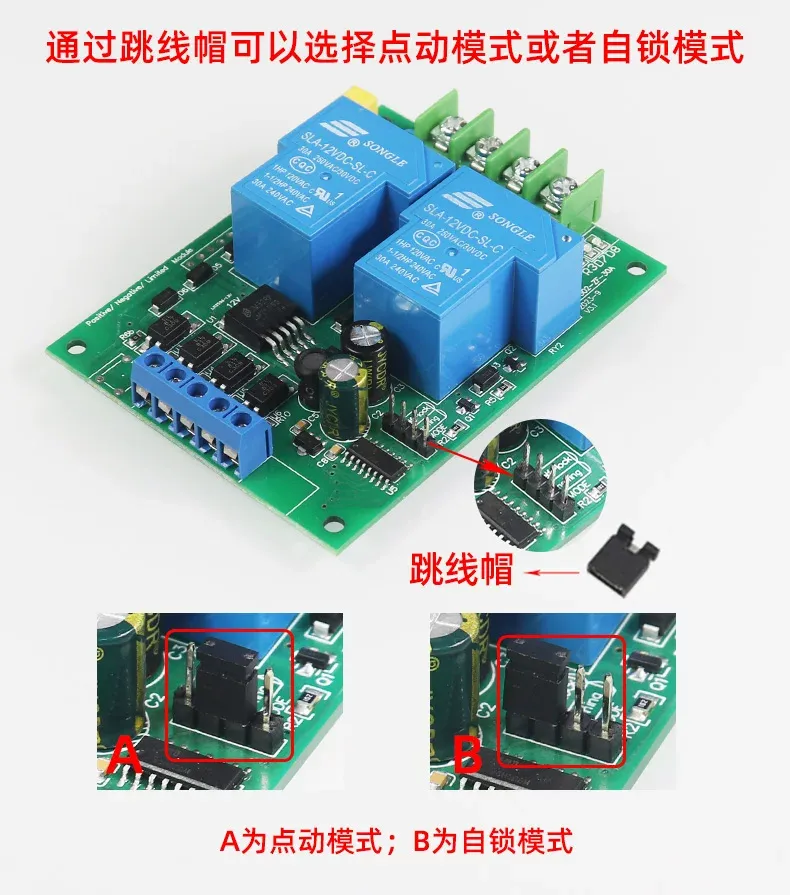
The MODE jumper cap selects jog mode or self-lock mode: jumper on position A is jog mode, on position B is self-lock mode.
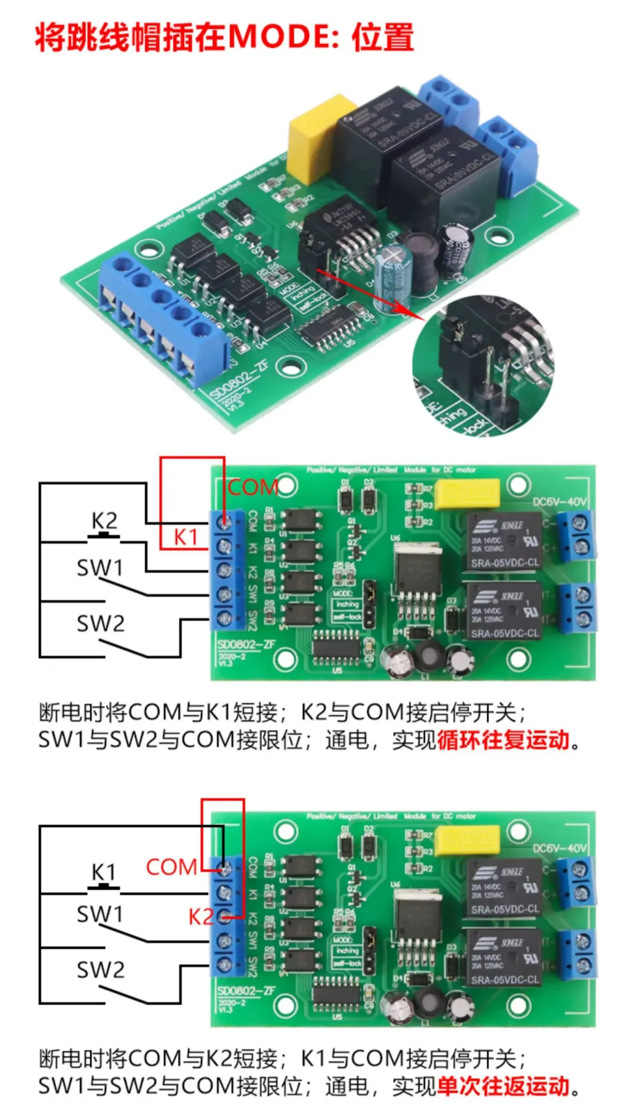
Reciprocating Motion Mode (Cyclic/Single-trip)
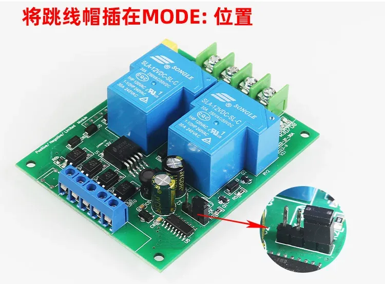
Insert the jumper cap on the MODE position to enable automatic reciprocating motion:
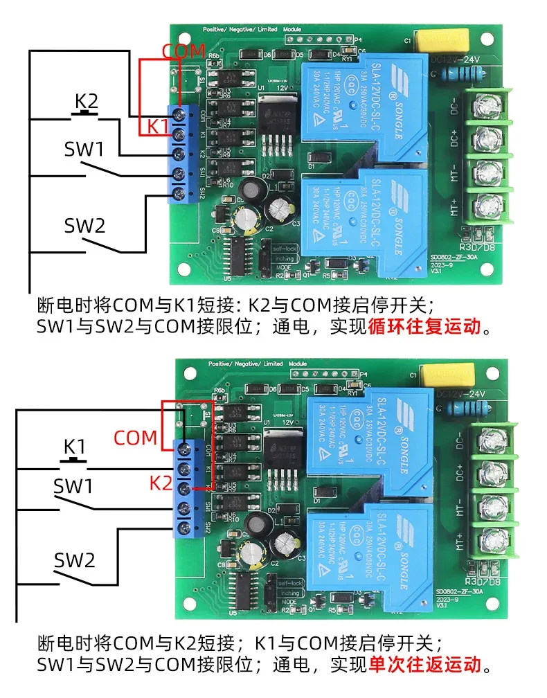
- Cyclic Reciprocating Motion: With power off, short COM to K1, connect K2 and COM to a start/stop switch, connect SW1 and SW2 and COM to limits; after power on, the motor reciprocates between the two limits.
- Single-trip Motion: With power off, short COM to K2, connect K1 and COM to a start/stop switch, connect SW1 and SW2 and COM to limits; after power on, the motor performs one reciprocating trip and then stops.
5A Version Complete Wiring Diagram
Hardware Features
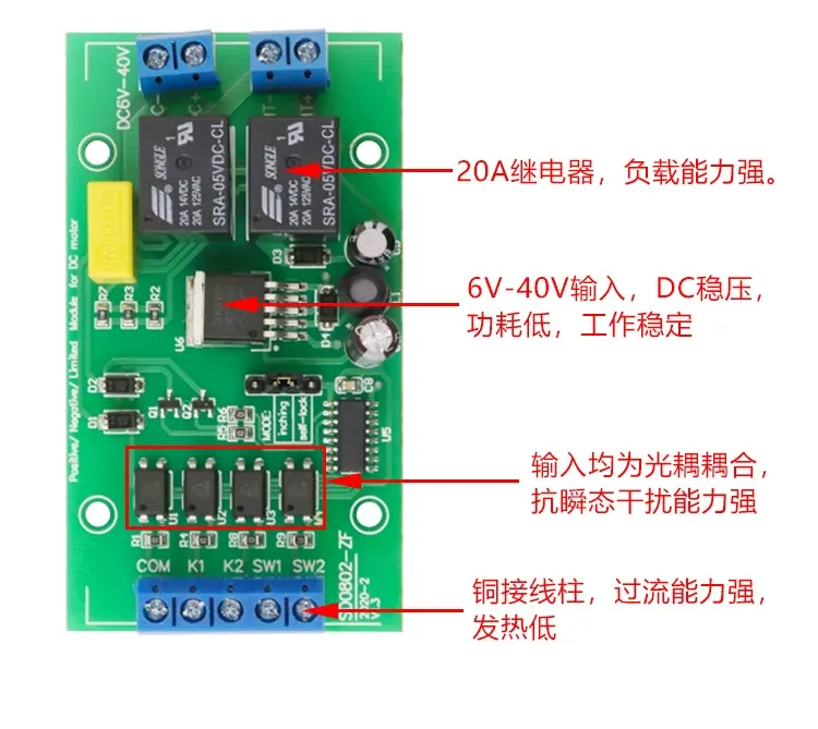
- 20A relay, strong load capacity;
- 6V-40V input, DC regulated, low power consumption, stable operation;
- All inputs optocoupler-coupled, strong transient interference resistance;
- Copper terminals, strong overcurrent capacity, low heat generation.
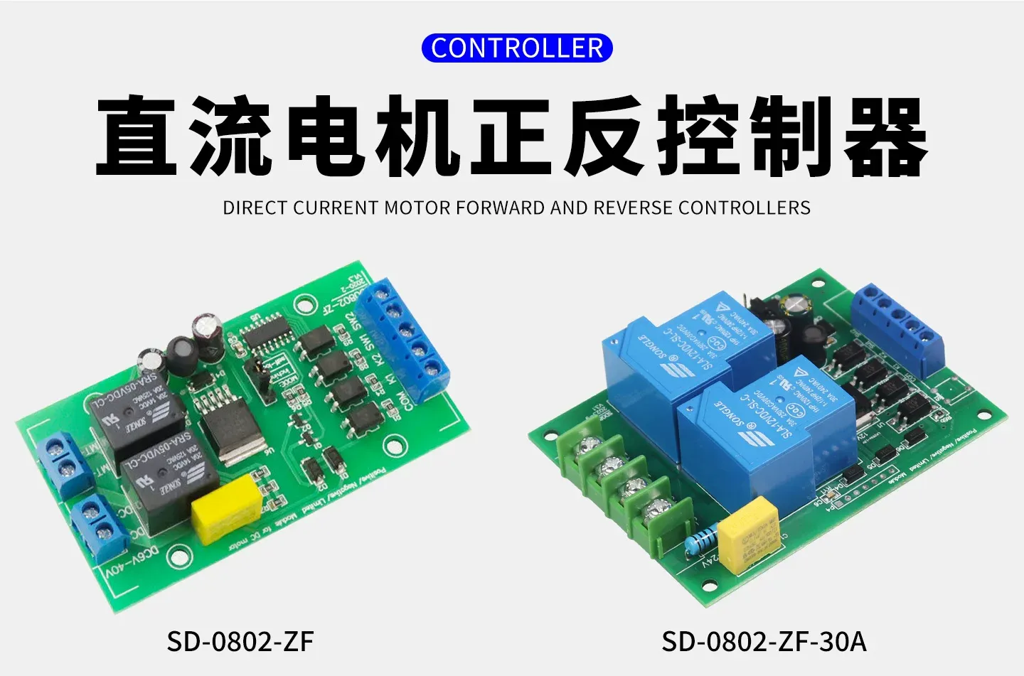
30A High-Current Version (SD-0802-ZF-30A)
The 30A version operates at DC12V-24V, rated power within 250W at 12V and within 350W at 24V, signal active low below 12V, with wiring and functions identical to the 5A version.
Using Sensors for Limit Detection
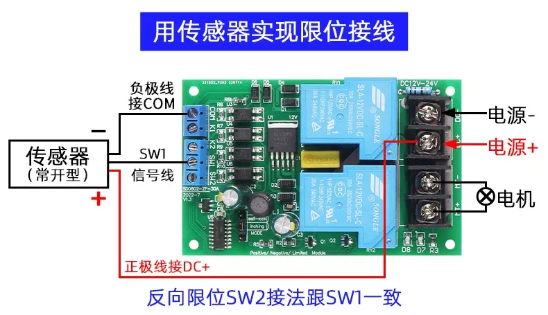
Besides mechanical travel switches, limits can also use three-wire NPN-NO (normally open) sensors: connect the sensor negative wire to COM, the signal wire to SW1 (or SW2), and the positive wire to DC+; the reverse limit SW2 is wired the same way as SW1.
FAQ
Q: What is the difference between self-lock mode and jog mode?
A: In self-lock mode, press K1 once and the motor rotates forward; releasing K1 it keeps rotating forward until a reverse signal K2 or the forward limit SW1 stops it; in jog mode, hold K1 and the motor rotates forward, release K1 and the motor stops immediately. The same applies to reverse.
Q: What are the signal requirements, can sensors be connected?
A: The signal is active low, and three-wire sensors (NPN-NO type) can be connected; K1, K2, SW1 and SW2 are all of this specification.
Q: Is the limit signal effective in jog mode?
A: Yes. For example, when K1 has a signal the motor rotates forward, but if SW1 limit also has a signal it will stop (it will not reverse).
Q: What is the limit signal like?
A: The limit signal can also be called a stop signal; it is trigger-type and level-enabled. During forward rotation, when a limit signal is encountered it stops, and even if the limit signal disappears it remains stopped; a new forward signal must be given again to rotate forward once more.
Q: What are the input and output voltages?
A: The input voltage adaptation range is 4V~40V; to ensure reliable operation it is recommended to use within 6V-36V; the output voltage is the same as the input voltage.
Q: What size motor can it drive?
A: The 5A version is suitable for DC brushed motors within 5A.
Product Dimensions
5A version: 83mm × 46mm, total height 20mm, mounting hole diameter 3.2mm; 30A version: 87mm × 68mm, total height 22mm, mounting hole diameter 3.2mm. Optional DIN-rail mounting enclosure (87.6×53.6×59mm) and wall-mount enclosure (90×90×40.5mm).