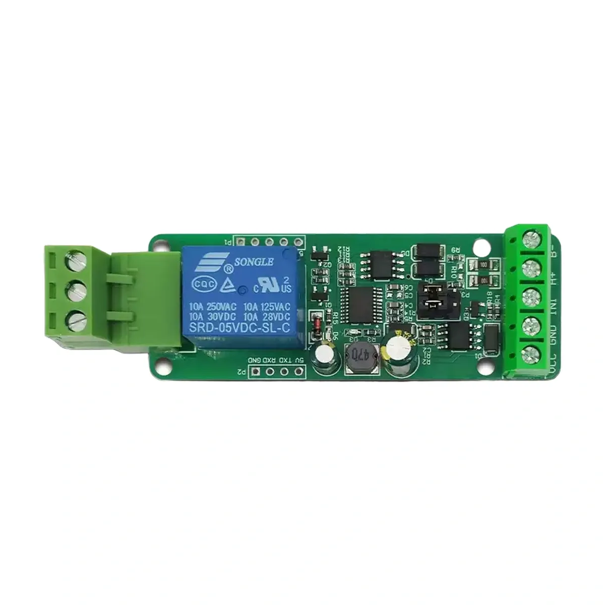
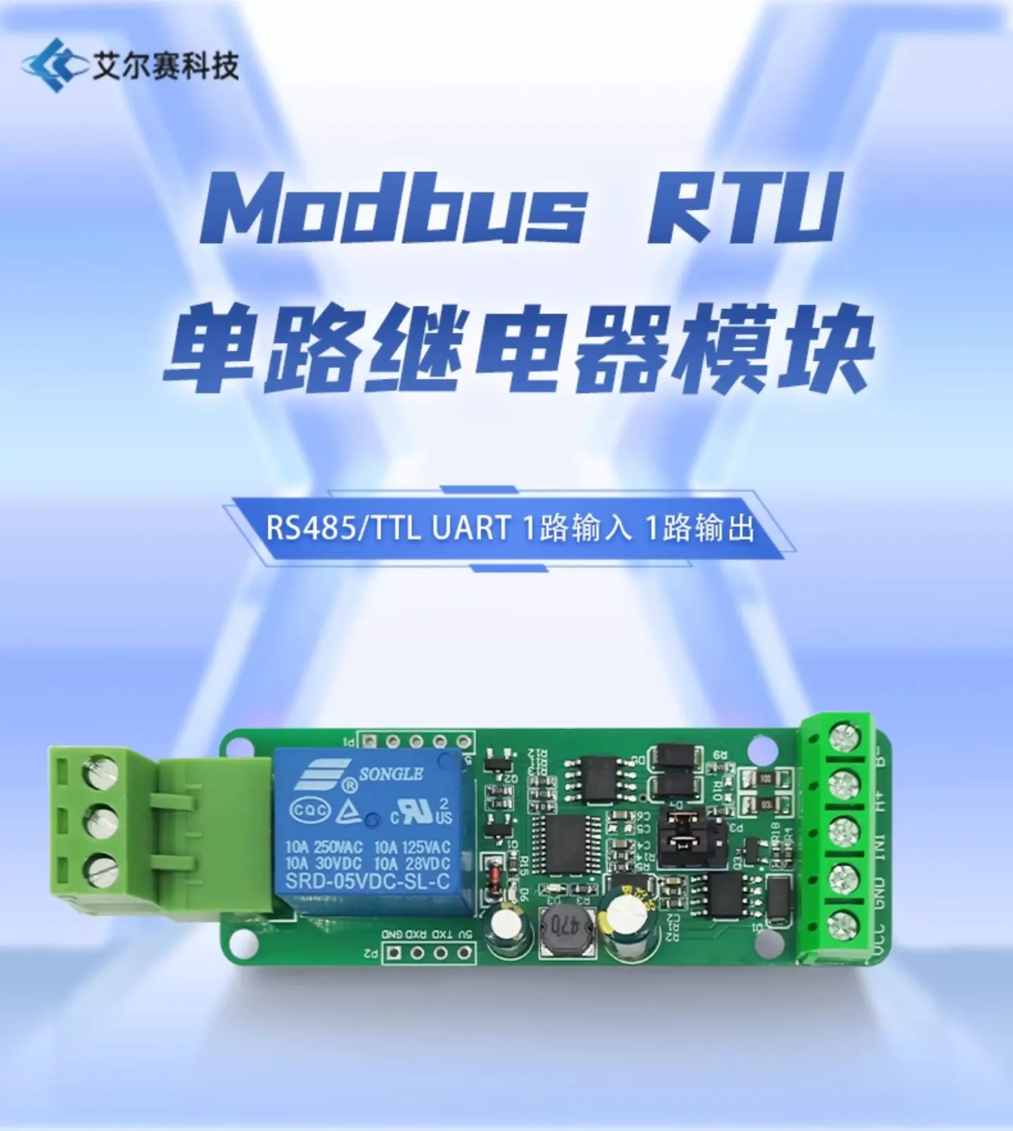
Modbus RTU Single-Channel Relay Module, RS485/TTL Dual Interface, 1 Optocoupler Input, 1 Relay Output, Wide Voltage DC7-24V, PLC & Microcontroller Linkage Control Board
Brief Description
Ailesai Modbus RTU single-channel relay module, supporting RS485/TTL UART dual-interface communication, 1 optocoupler input for signal detection + 1 relay output (10A/250VAC, 10A/30VDC), wide voltage DC7-24V power supply with reverse-polarity protection, baud rate and device address retained after power loss, and three output modes: manual / pulse-on / pulse-off. Ideal for digital signal detection, power control, PLC/host computer/microcontroller linkage control and other industrial automation and IoT applications.
Quantity
Product Overview
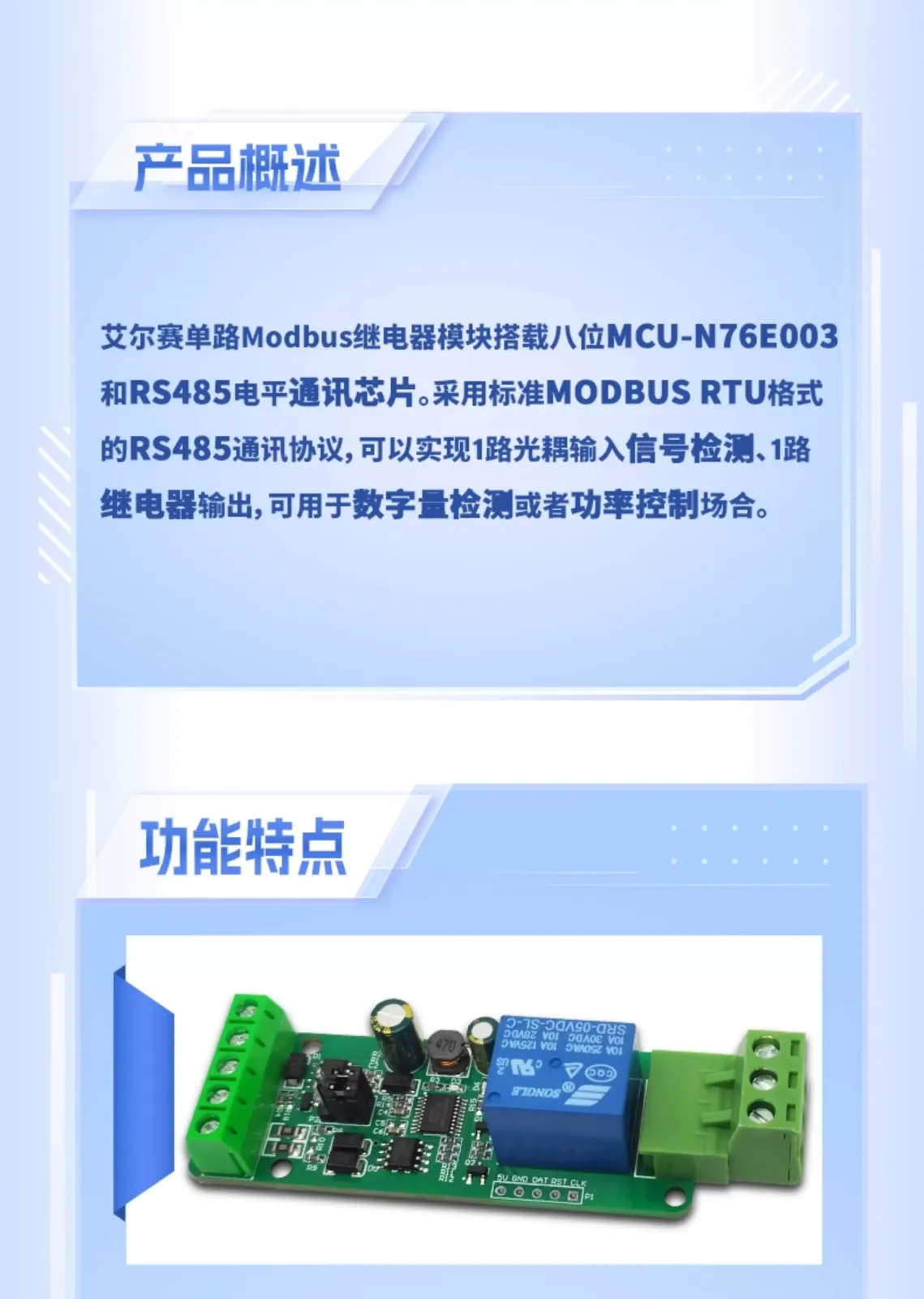
The Ailesai single-channel Modbus relay module is built around an 8-bit MCU-N76E003 and an RS485 level communication chip (MAX485). It uses the standard MODBUS RTU RS485 communication protocol and supports 1 optocoupler input for signal detection plus 1 relay output, making it suitable for digital signal detection or power control applications.
Features
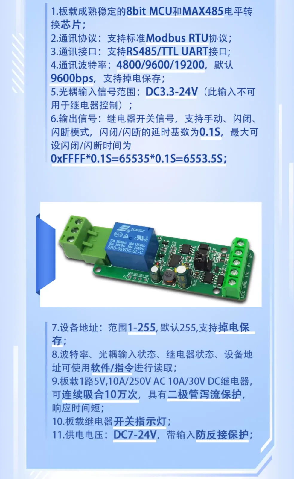
- Onboard proven and stable 8-bit MCU (N76E003) and MAX485 level conversion chip;
- Communication protocol: supports standard Modbus RTU protocol;
- Communication interface: supports RS485 / TTL UART interface;
- Baud rate: 4800/9600/19200, default 9600bps, retained after power loss;
- Optocoupler input signal range: DC3.3-24V (this input cannot be used for relay control);
- Output signal: relay switch signal, supports manual, pulse-on and pulse-off modes; the delay base for pulse-on/pulse-off is 0.1S, and the maximum settable pulse-on/pulse-off time is 0xFFFF*0.1S=65535*0.1S=6553.5S;
- Device address: range 1-255, default 255, retained after power loss;
- Baud rate, optocoupler input status, relay status and device address can be read via software/commands;
- Onboard 1-channel 5V, 10A/250V AC, 10A/30V DC relay, capable of 100,000 consecutive operations, with diode flyback protection and fast response time;
- Onboard relay switch indicator light;
- Supply voltage: DC7-24V, with input reverse-polarity protection.
Technical Specifications
| Item | Specification |
|---|---|
| Main control chip | 8-bit MCU N76E003 |
| Communication chip | MAX485 level conversion |
| Communication protocol | Standard Modbus RTU |
| Communication interface | RS485 / TTL UART |
| Baud rate | 4800 / 9600 / 19200 bps, default 9600, retained after power loss |
| Optocoupler input | 1 channel, DC3.3-24V (cannot be used for relay control) |
| Relay output | 1 channel, 10A/250VAC, 10A/125VAC, 10A/30VDC, 10A/28VDC |
| Output modes | Manual / pulse-on / pulse-off, delay base 0.1S, max 6553.5S |
| Device address | 1-255, default 255, retained after power loss |
| Supply voltage | DC7-24V, input reverse-polarity protection |
| Relay life | 100,000 consecutive operations, diode flyback protection |
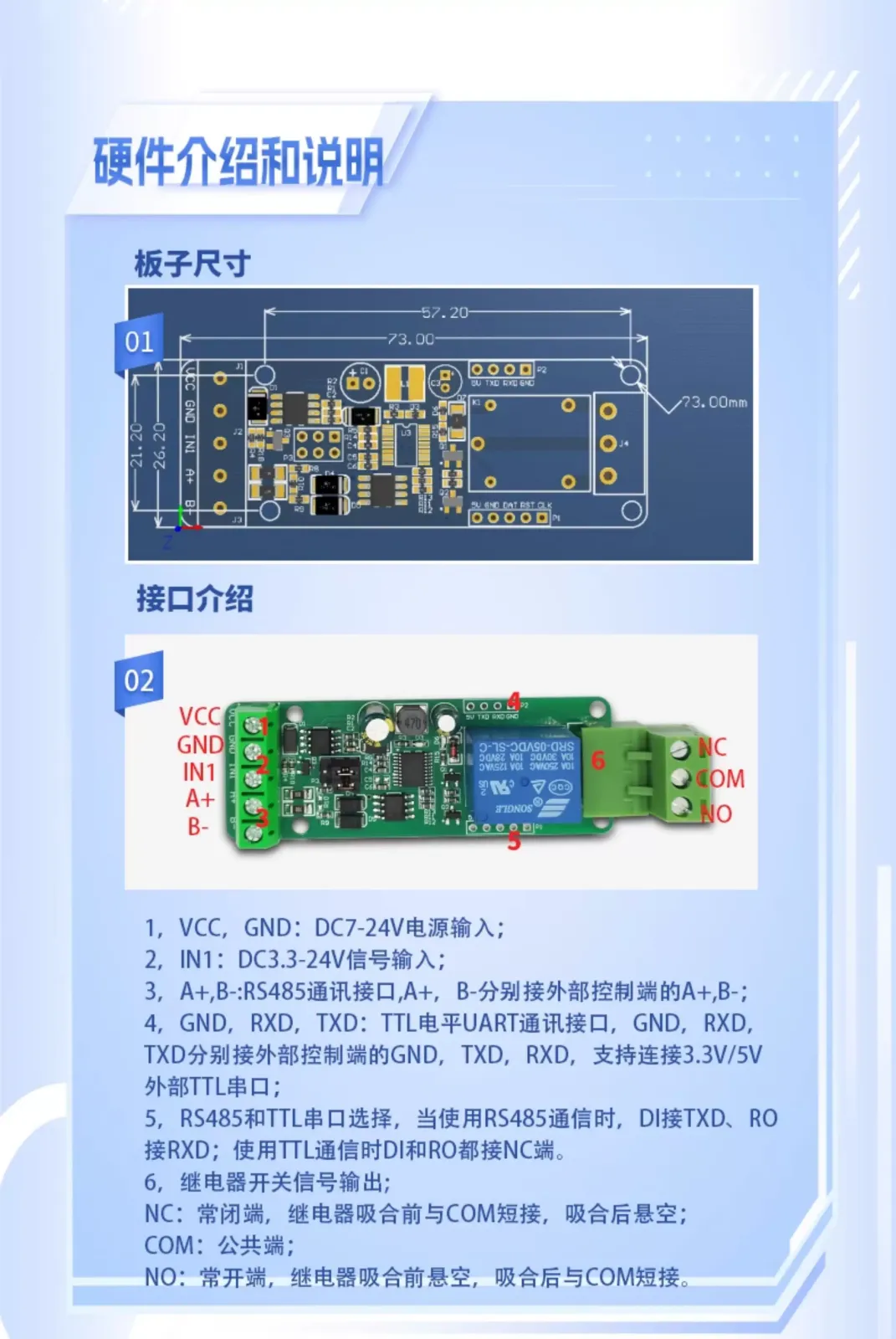
| Board dimensions | 73.00 × 23.00 mm, plug-in terminal blocks |
Interface Description
| Terminal | Description |
|---|---|
| VCC / GND | DC7-24V power input |
| IN1 | DC3.3-24V signal input |
| A+ / B- | RS485 communication interface, connects to external controller A+ and B- |
| GND / RXD / TXD | TTL level UART communication interface, supports connection to 3.3V/5V external TTL serial port |
| NC / COM / NO | Relay output: NC normally closed, COM common, NO normally open |
RS485 vs. TTL serial selection: When using RS485 communication, connect DI to TXD and RO to RXD; when using TTL communication, connect both DI and RO to the NC terminal.
Modbus RTU Command Overview
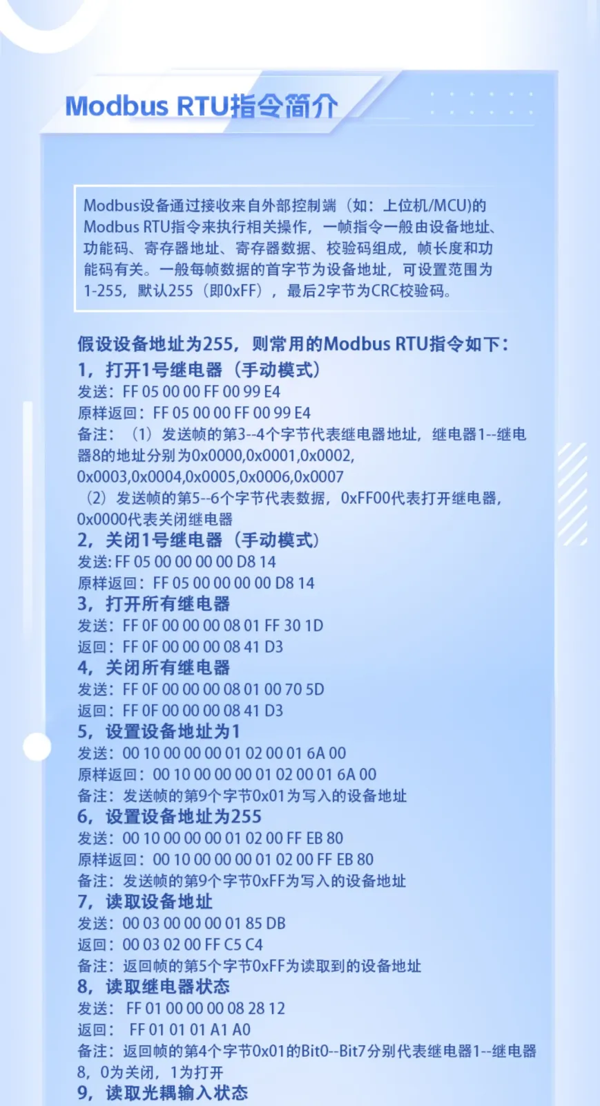
Modbus devices perform operations by receiving Modbus RTU commands from an external controller (such as a host computer/MCU). A command frame generally consists of device address, function code, register address, register data and checksum, and the frame length depends on the function code. The first byte of each frame is the device address, settable from 1-255, default 255 (i.e. 0xFF), and the last 2 bytes are the CRC checksum.
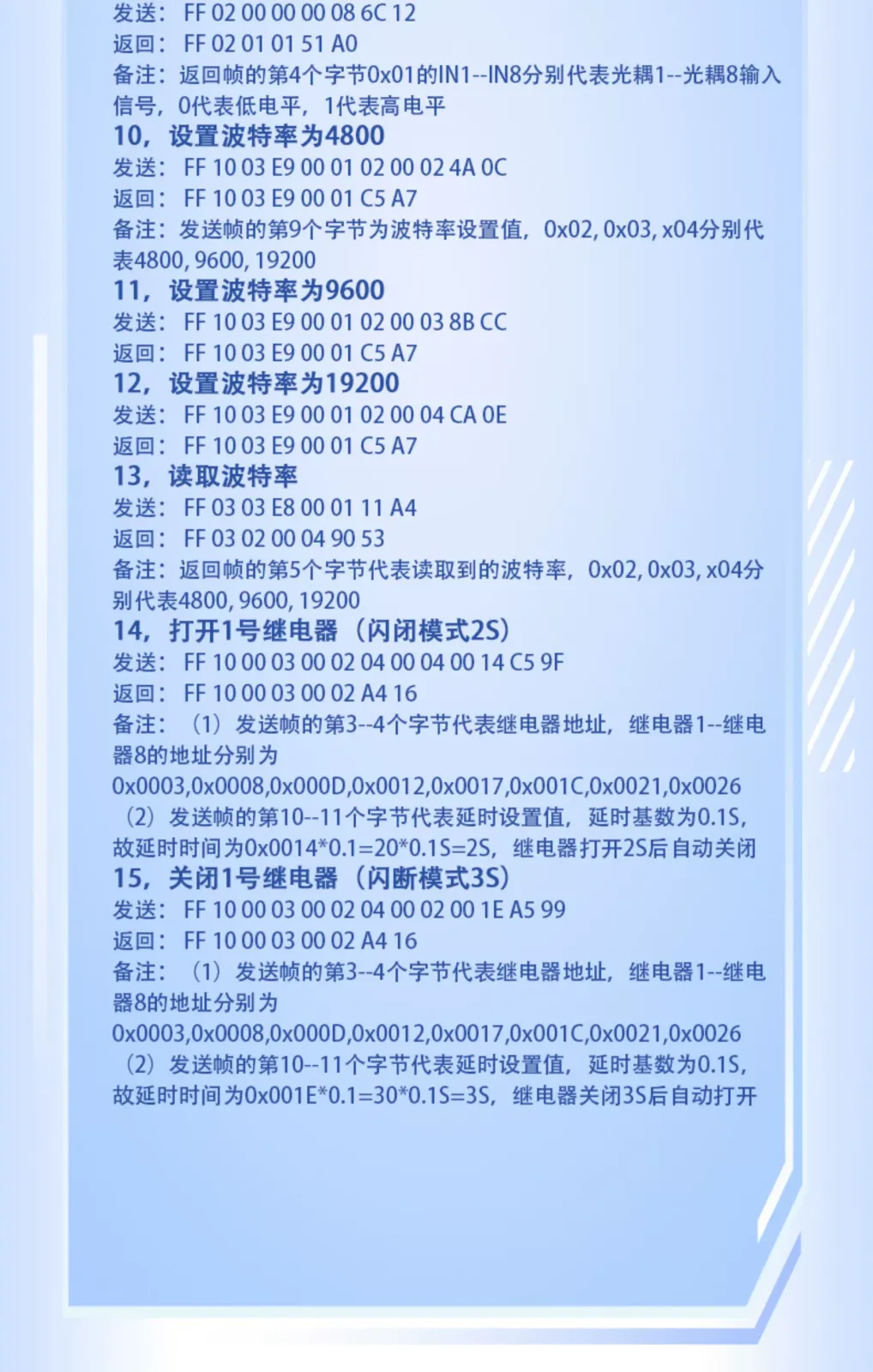
Common command examples (device address 255): to turn on relay 1 (manual mode), send FF 05 00 00 FF 00 99 E4; to turn off relay 1, send FF 05 00 00 00 00 D8 14; to read relay status, send FF 01 00 00 00 08 28 12; to read optocoupler input status, send FF 02 00 00 00 08 6C 12. Commands can also be used to set the device address, baud rate (0x02/0x03/0x04 represent 4800/9600/19200 respectively) and pulse-on/pulse-off delay.
Quick Start Guide
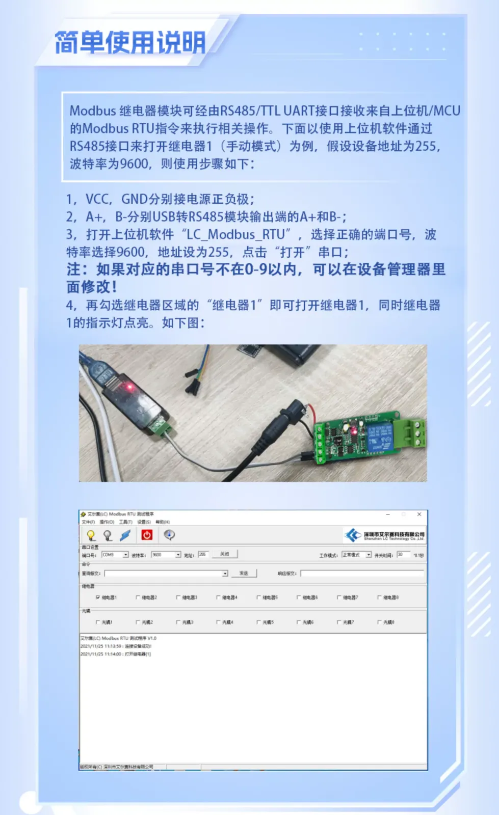
- Connect VCC and GND to the positive and negative terminals of the power supply respectively;
- Connect A+ and B- to the A+ and B- outputs of a USB-to-RS485 module respectively;
- Open the host software \"LC_Modbus_RTU\", select the correct port number, set the baud rate to 9600, set the address to 255, and click \"Open\" to open the serial port (if the port number is not within 0-9, you can change it in Device Manager);
- Check \"Relay 1\" in the relay section to turn on relay 1, and the relay 1 indicator light will turn on at the same time.
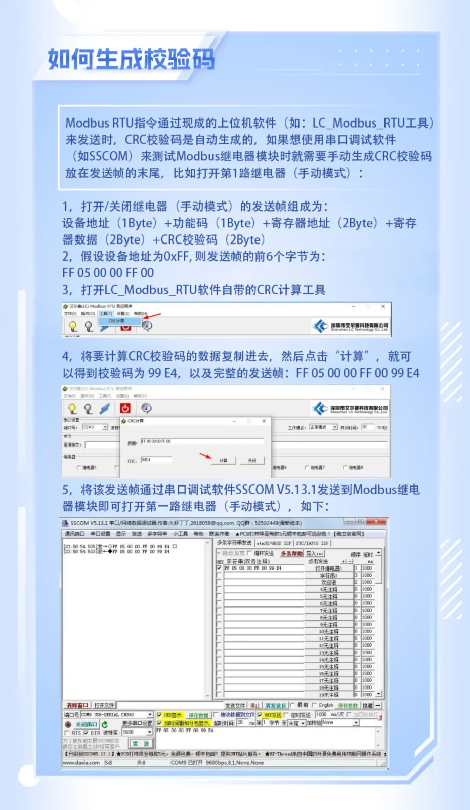
How to Generate the Checksum
When sending commands with ready-made host software (such as the LC_Modbus_RTU tool), the CRC checksum is generated automatically; if you need to test with serial debugging software (such as SSCOM), you must manually generate the CRC checksum and place it at the end of the send frame. The send frame for turning the relay on/off (manual mode) consists of: device address (1 Byte) + function code (1 Byte) + register address (2 Bytes) + register data (2 Bytes) + CRC checksum (2 Bytes). For example, with device address 0xFF, the first 6 bytes are FF 05 00 00 FF 00, and using the CRC calculation tool included with LC_Modbus_RTU gives the checksum 99 E4, so the complete send frame is FF 05 00 00 FF 00 99 E4.
Package Contents
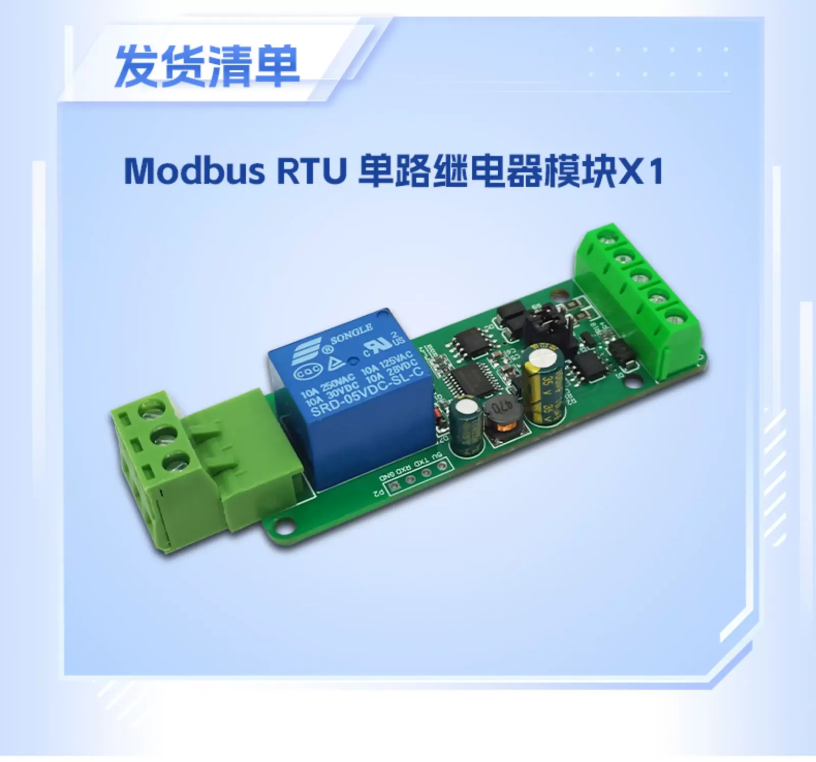
Modbus RTU single-channel relay module × 1
FAQ
Q: Can the optocoupler input IN1 directly control the relay?
A: No. IN1 is only used for DC3.3-24V optocoupler input signal detection; the relay output is controlled by Modbus RTU commands.
Q: Which host software is supported?
A: It comes with the LC_Modbus_RTU test program, and you can also use serial debugging software such as SSCOM to send commands according to the Modbus RTU protocol.
Q: Will settings be lost after power off?
A: No. Parameters such as baud rate and device address are retained after power loss.